Step 1
Preparing the Game Module Circuit Board
|
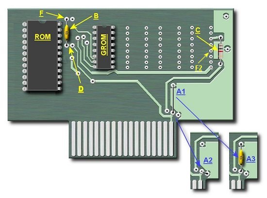
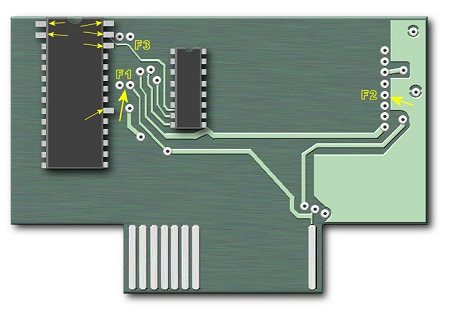
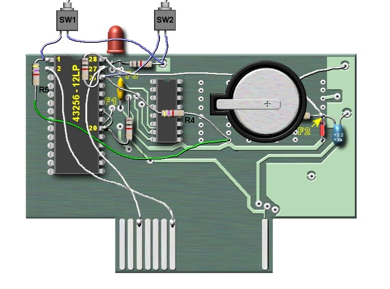
The above picture is a typical game module circuit board as described above in the parts table.
I did not draw in all the foil on the circuit, but enough to show where everything is, and where everything goes. Some modules
may contain up to 4 grom chips.
Notice that the "A's" are marked A1, A2, and A3. Depending on which game module you use you will have
one of the configurations shown. If you have just the wires, as shown in A1 or A2 then you will not need to
do anything, as this part of the board is ready. If, however, you have a capacitor as shown in A3 you will
need to remove this capacitor and replace it with a wire so that it looks like A1.
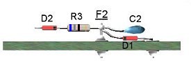
Remove the capacitor marked "B" and set aside, we will use this capacitor later.
Remove the resistor marked "C", we will NOT be using this resistor.
Remove the small piece of foil that links the two solder holes at "D". You can use a small knife to do
this, and just make sure that you remove enough of the foil so that the two solder holes are electricly
seperated.
Remove any AND all foil connections to the solder hole shown as "F2". You will need to do this on both sides
of the circuit board, but the back side should be a dot that is not going anywhere. This solder hole
will only be used to attach some components together. Just make sure
that it is isolated from any foil connections on the circuit board.
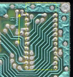
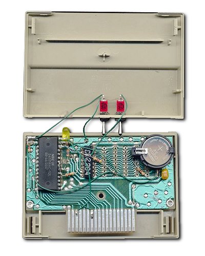
We will now remove some more foil. It is marked as "F" above. This time it will be done on the back of the circuit board. The pictures
below show the back of the circuit board, and the two yellow arrows are pointing at the area of foil that
needs to be removed. The yellow dotted box, is the where the ROM chip was installed and it is just shown for
reference.
|

|
|
|
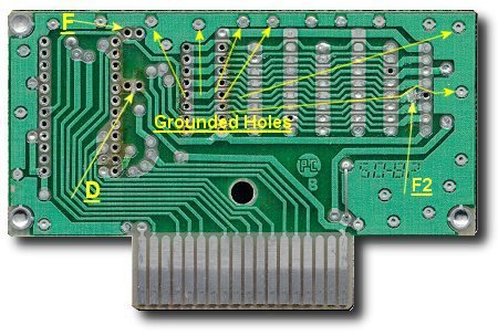
The above picture shows the circuit board with all the modifications done. It is now ready to be used to create
our 8K Supercart.
|
Step 2
Assembling the Supercart
|
 |
|
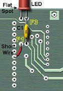
Solder the LED into the two F3 holes. Note that the flat spot on the LED goes into the
left hand hole.
Solder one end of C1 (this is the capacitor which came with the cartridge) into the right hole of
the F1 pair. Solder the other end to the LED as shown on the left.
Next solder a short wire from the 6th pin hole up to the left hole on the F1 pair. This pin on the RAM
IC we will be using will be bent up so there is no problem using this hole.
|
 |
|
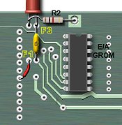
Solder one end of R2 (1K resistor) to the left wire of the LED as shown. Make sure that you bend R2's
lead so it does not touch the LED's other lead. Then solder the other lead of R2 to any
of the grounding holes located accross the top of the board.
Next solder in the Grom IC which was
removed from the E/A cartridge. Make sure the notch on the IC is pointing up as shown.
|
 |
|
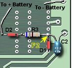
Now we move to the right side of the circuit board. This is the battery backup part of the circuit.
Start by soldering the + lead of C2 into the hole marked "F2". Then solder the - lead of C2 to a grounding
hole as shown.
Next solder the unbanded end of D1 into the hole as shown, and then solder the banded end to the positive lead
of C2 which is at "F2".
Solder one end of R3 (68 ohm resistor) to "F2" and solder the banded end of D2 to the other end of R3. Keep the wire short on
the banded end of D2 as the lead on the D2 is not that heavy.
|
 |
|
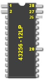
The RAM IC (43256-12LP) is CMOS device, which means you need to be very careful handling it. Follow all ESD rules
when working with this IC. Make sure you ground yourself by either touching a large metal item, or by
wearing a grounding strap.
The first thing we need to do with the RAM IC is to bend some pins out. The picture on the left shows which
pins need to be bent out. You may also need to bend all the pins on the IC in a little to fit in holes in
the circuit board.
Place the RAM IC into the circuit board as shown below. Solder in all pins on the bottom of the board, taking
care not to overheat the IC. I usally solder a pin or two and then blow on the pins I just soldered to
keep everything cool. Better to to be slow and easy soldering in this IC.
|
|
|
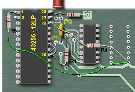
Next we need to solder a 4.7K resistor (R4) from +5volt to pin 26 of the RAM IC
as shown in the picture to the left.
Now solder a 4.7K resistor (R5) to pin 1 of the RAM IC and to the same +5 volt connection as shown.
Solder one lead of R1 (1K resistor) into the hole as shown above and the other lead of R1 to pin 20
of the RAM IC.
Solder a short wire (or use the lead of R1) from pin 20 to pin 22.
|
|
|
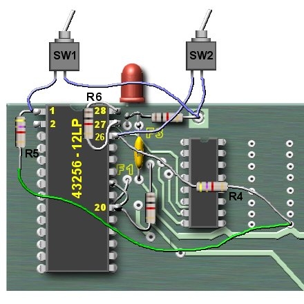
Now we will connect the two switches which will choose which of the 4 banks we will be working with.
Solder one connector from switch 1 to pin 1 of the RAM IC. Solder the other connector to ground, as shown.
Solder one connector from switch 2 to pin 26 of the RAM IC. Solder the other connector to ground, as shown.
Now solder a 1K resistor (R6) to pins 27 and 28 and the RAM IC.
|
We are getting close now! Double check all your solder joints to make sure you did not bridge any connections.
Use of a bright light and a magnifier is very helpful here.
Solder a wire from pin 2 to the 7th edge connector pin as shown above.
Solder a wire from pin 27 to the 3rd edge connector pin.
Solder a wire from 28 to "F2"
The last step is to connect the battery holder. DO NOT place the battery into the holder at this time!
Solder the unbanded end of D2 to the positive post of the battery holder, and solder the negative post of the
battery holder to a grounding hole.
Again, double check all wiring, and connections. Make sure you have pins 26, 27, and 28 of the RAM IC bent up
enough so they are not near the wires around the LED.
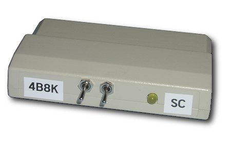
Below is an actual picture of my finished cart.
|
Step 3
Testing the Supercart
|
Before testing let's take a moment and see how to use the two switches to change banks.
Bank 1 = 0,0 (both switches closed)
Bank 2 = 0,1
Bank 3 = 1,0
Bank 4 = 1,1 (both switches open)
To test all banks you will need to perform the below tests on each bank by using the switch patterns above.
(This is actually the test for the standard 8K supercart)
For each bank I would change the numbers from 1,2,3,4 as shown below to 1,1,1,1 for bank 1, 2,2,2,2 for bank 2
so forth.
One last thing, which has happened to me. If I power down the the supercart while in bank 3,
as an example it sometimes messes up. It works fine if I kick out to the title screen before powering down. Just
wondering if anyone might know if this is just the nature of the beast.
Make sure that that your PEB and Monitor are powered up, but not the conosle at this time. Insert the supercart
module into the module slot in the console (it does not need to be in the case). Make sure that the LED comes on.
If it does not, or anything else wierd happens, turn off the console and check the supercart for any shorts, or
bridged connections.
If the LED lights and everything seems ok go to the TI BASIC screen and type this in:
CALL LOAD(24576,1,2,3,4)
CALL PEEK(24576,A,B,C,D)
PRINT A;B;C;D
You should see 1 2 3 4 on the screen. If you do, so far so good!
Now power down the console and remove the supercart. Install the battery into it's holder, making sure that
the + of the battery is facing up.
Place the supercart into the console and power up the console again.
At the TI BASIC screen again type:
CALL LOAD(24576,1,2,3,4)
CALL PEEK(24576,A,B,C,D)
PRINT A;B;C;D
Again, you should see 1 2 3 4 on the screen.
Now power down the conosle and wait a few minutes.
Power up the console and at the TI BASIC screen type:
CALL PEEK(24576,A,B,C,D)
PRINT A;B;C;D
If you see 1 2 3 4 again, then your battery backup is working!
|
Step 4
Installing in the Cartridge Case
|
The last step is to install the circuit board into the case. The first thing I did was to put some electrical
tape underneath the batter holder, and anywhere else a wire might come in contact with the circuit board.
The only modification that needs to performed on the case is a hole for the LED and the two switches. You can lay the circuit board
in the case and mark where the LED will be. Then using a drill, dremel, or an old soldering iron, make a hole
for the LED and the two switches.
That's it.. you now own a 4 Bank SUPERCART!!!
NOTE:
"To maximise battery life, do not leave the cartridge plugged into the console when powered off for any
length of time. Left in the console (powered off), the battery will go flat in a couple of weeks. Removed from
the console, the battery should last a couple of years."
Thanks to Stuart Conner for this great info!
|
Step 5
Using the Supercart
|
The following article appeared in the July 1985 MICROpendium and was written By DAVID R. ROMER
You can alter assembly language software so that it may be run out of your RAM chip enhanced Editor/Assembler cartridge (SUPERCART) as a powerup menu selection.
Using information in this article, in essence you will be able to create your own cartridge, containing your own programs, runnable at the press of a single key.
The basic steps to convert software for Supercart use are:
1. Move DEFinition statements to the beginning of the program.
2. Absolute ORGin the program at >6000
3. Substitute stand-alone routines for external REFerences to cartridge utilities.
4. Add the CARTRIDGE HEADER to the source code so the powerup routine will place your program on the menu screen.
To take a closer look at these steps let's examine the following example program called TEST. If you enter, assemble and load program TEST into your SUPER CART, selection 3 on the menu screen should say 'MENU TEST'. When 3's pressed, the screen will clear and the text "MENU TEST PROGRAM" will be displayed briefly, followed by a return to the color bar screen.
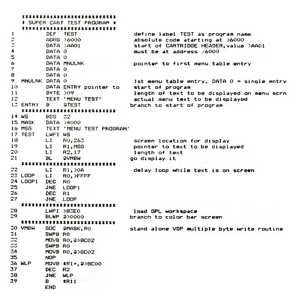
Line 1 is the usual DEF statement setting the entry point or points to the program. DEF statements do not have to be at the beginning of a program as long as they precede the first reference to the DEF label. However, since the first reference to the entry point in our SUPER CART software will be in the CARTRIDGE HEADER, line 13 in TEST, it will be necessary to place the DEF statement first in the program.
Any external REFerences to utility routines must be removed from the program. Since there is no CALL INIT sequence prior to executing the cartridge program, utilities such as VMBW, KSCAN, DSRLNK, etc., are not available to your SUPER CART program. In a third article I will describe a routine that will make the cartridge utilities available to your SUPER CART program. Likewise, a program originally written to run from Mini-Memory will reference those utilities through EQU statements. Those EQUates must be removed from the source code. Since we are not In the Mini-Memory environment these routines do not exist at the EQU addresses. If the utilities are required in your SUPER CART program then stand-alone routines must be added to the source code. In our example program lines 30 to 39 are a stand-alone Multiple Byte Write routine used to display the text line 16 on the screen.
The 8K RAM chip you added to your E/A cartridge uses memory addresses >6000 to >7FFF. While a cartridge program could be located anywhere within those addresses, the CARTRIDGE HEADER must start at
>6000. Since we are adding the HEADER to existing source code, an AORG >6000 statement, as in line 2 in TEST, will cause the LOADER program to place your program at that address so that it may be executed from the menu screen. All other AORG statements should be removed from the source code. Do not assume that DEF, REF, EQU and AORG statements occur only at the beginning of source code. You Can Save yourself some assembly time if you use the FIND function in the EDITOR to search all of the source code for occurrences of those statements.
Lines 3 to 13. in program TEST, make up the CARTRIDGE HEADER code that enables the powerup routine to include and execute your program from the menu screen. Lines 3 to 13 MUST load starting at >6000. The only source code statements that can precede the CARTRIDGE HEADER are DEF, AORG or EQU statements. In line 3 the value >AA will load at >6000 and tells the powerup routine that a valid cartridge is in the cartridge slot. The value >01 indicates that the cartridge contains executable machine code. Lines 4 and 5 set the next two memory words to 0. Line 6 can be any valid label and is a pointer to the first entry in the menu table.
Line 9 is the menu table entry pointed to by line 6. In program TEST it is set to 0 as there is only one entry point into TEST. If there were additional entry points or multiple programs, line 9 would point to the next menu item (e.g. MNULNK( DATA NXTLNK). The menu screen would appear to have room for seven or eight selections. Line 10 is a pointer to the start of the program. Line 11 is a byte value that is the length of the text to be displayed on the menu screen. Line 12 is the text to be displayed. Finally, line 13 is the Branch to the start of the program.
Once you have made these changes to your source code, assemble it, then load it Into your SUPER CART with Opt. 3 LOAD and RUN on the Editor/Assembler menu.
You may also load your SUPER CART from TI-BASIC with CALL INIT then CALL LOAD("DSK1.YOURPROG"). Press Function Quit to return to the color bar screen, press any key and your program should appear as selection 3 on the menu. For those of you who maybe using the Cor-Comp disk controller and SUPER CART with a program having multiple entry points, you will find that the Cor-Comp screen will display only the first entry in the menu table. However, pressing the space bar twice will display the TI screen that will show all of the menu selections you have added to your SUPER CART. The best part of it is that your program will still be there ready to go until either the battery quits or you change the program.
Those are the basic steps required to after software to run out of your SUPER CART. Some programs may require only the addition of the CARTRIDGE HEADER and others may
require extensive revision to substitute stand-alone utility routines. The possibilities are limited only to one's imagination, and 8K of memory. By the way, this article was written with a SUPER CART containing the TK-Writer loader for TI-Writer. The menu screen has five selections:
1. TI-BASIC
2. Editor/Assembler
3. 1K-Editor
4. TK-Fonnat
5. TIC-Utility
TX-Writer is a very easy conversion. You only have to add AORG >6000 and the CARTRIDGE HEADER.
|