 |
PEB Disassembly
and "Quiet" Fan Installation
|
This is an easy, inexpensive project that gets rid of the "noise" that the PEB makes. You only need simple soldering
skills, and most of the work is just getting the PEB apart.
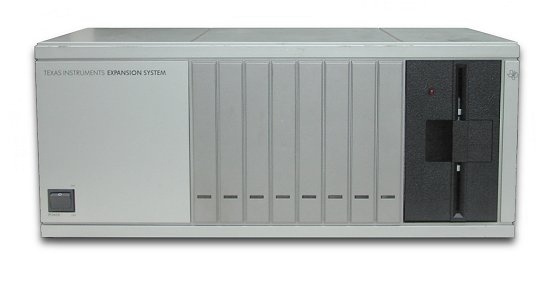
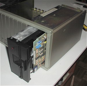
Pictured is a standard TI Periphial Expansion Box. There is nothing "difficult" with taking one apart,
just a lot of screws to take out. You will need a number "1" phillips screwdriver, as the standard number "2" '
is just a bit too big.
You can order this fan here.
|

|
|
*** You will be working with 110 volts in this project so it is very important that you remove the
power cable from the PEB before going any further.***
Please make sure that all wiring and soldering is double checked before re-applying power. Though computer components are pretty hardy some do not take to being
wired up backwords or incorrectly. I have done my best to make sure that all diagrams
and instructions given here are correct, but I can not be responsible for any damage
an incorrect upgrade might cause. Also keep in mind that this will probably void any warranty :>).
|
The first step is to remove the top cover, by pressing in the two clamps on the back of the PEB.
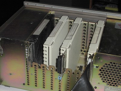
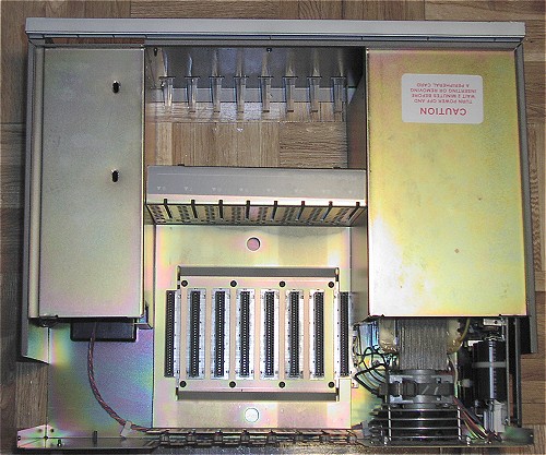
This picture shows the cover removed from my PEB. I have 4 cards in mine, a 32k memory card, an RS232 card,
the peripheral expansion card, and the disk memory system card. The two center cards are removed by simply
pulling them up. The other two cards require a little more effort.
|
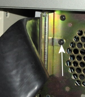
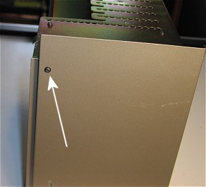
To remove the peripheral interface expansion card (the one with the "firehose" attached), you must remove the
screw which holds it's bracket to the PEB. The picture above shows the location of this screw. After
removing the screw you may then remove the entire card taking care not to overly strain the "firehose".
|
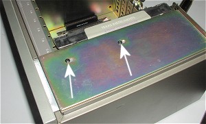
To remove the disk memory system card you must first remove the floppy drive. The floppy drive is held
in place by 4 screws. The above picture shows 2 of the screws which are located on top of the PEB. There are
2 additional screws located on the bottom of the PEB.
|
Slide out the floppy drive being careful to only pull it out far enough to reach the two connectors.
|
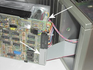
The above picture shows arrows pointing at the 2 connectors (cables) which need to be removed
from the drive. One is the power connector and the other is FD controller cable. Both of these
connectors are "keyed" so they will only go back one way.
|
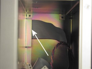
One last step needs to be performed before removing the disk memory system card. The picture shows
what you should see when you look into slot the floppy was in. An arrow points to end of the
floppy cable, and this cable needs to be removed from the card. Put your hand into the slot
and grasp the end of the cable and pull it to the right. Sometimes these cables can be a little tight.
Now you can remove the disk memory system card. This end of the cable is also "keyed" so you might make
note of which way the key goes as you can tell, this is a bit of a tight fit.
|

Now grab your trusty phillips screwdriver and prepare to remove the screws holding the PEB together. One
thing you must say about TI, they sure built heavy duty equiptment. The above picture shows the bottom
of the PEB and the arrows show the location of the screws.
|
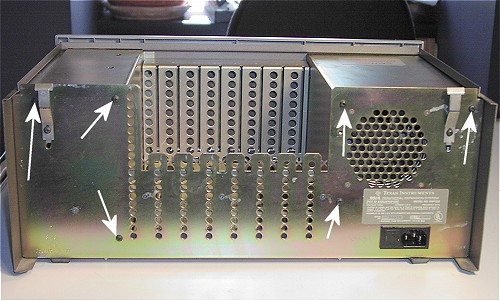
Next place the PEB so you can reach the back of it. Again, remove the 6 screws shown by the arrows.
|
There are 2 more screws to be removed which are located on the side of the PEB.
|
The above picture shows the two main pieces of the PEB being separted. Of course we are interested
in the half which holds all the electronics.
|
|
*** Again, make sure that you have no power cord in the PEB ***
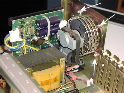
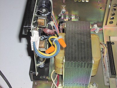
The above picture shows the power supply circuit board, the very heavy transformer, and, of course,
the fan. The arrows are pointing at the 4 nuts (one can't be seen) that hold the fan secured to the PEB.
The last screw is a bit tough to get to due to the circuit board. I found it much easier to get to everything
by un-doing the mounting for the circuit board which the below picture shows.
|
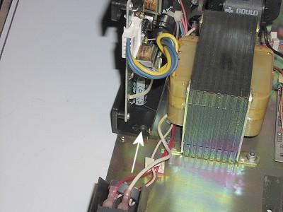
There are 2 screws which hold the plastic frame which in turn holds the circuit board. The arrow shows
one of the screws with the other being located on the other side. You don't need to remove the screws,
just loosen them a little and then move the circuit board a little out of the way.
|
Remove the original fan. Even though the fan has some sort of connectors I found it much easier to just
cut the wires and place wire nuts over the them. I then used a wire tie to fasten them down. Keep in mind
that these wires do carry 110 volts, so be careful how you secure them. YOU WILL NOT USE THESE WIRES
TO POWER THE NEW FAN. The new fan only requires 12 volts NOT 110 volts.
|
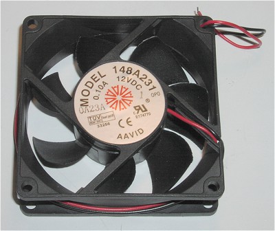
This is a picture of the Fan that John supplied me for this project. You want to make sure that
the fan exhausts out of the PEB, and the fan does have an arrow on the top which shows the direction
of the air flow. This fan is a 25 db 28 cfm model rated at .10 amps, and runs on 12 volts dc.
|
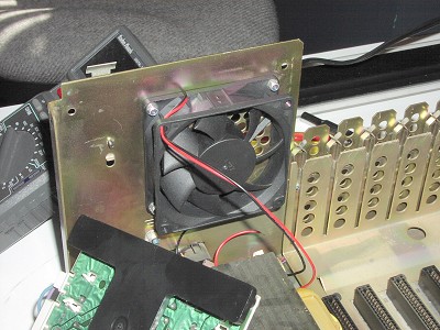
This pictures shows the fan mounted to the PEB. You just use the same nuts and bolts that
held the original fan. Notice that the label on the fan points away from
the power supply. Again, this makes the fan "blow out".
|
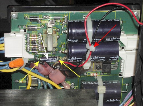
Now we must find a way to provide the 12 volts DC to the fan. There is a regulated 12 volts provided at the
positive and negative ends of the C18 (marked by white arrow) located on the power supply which makes it a rather
simple task to wire the fan. The above picture shows a close-up of the two fan wires soldered to the
capacitor. The yellow arrows point to where I soldered the wires. The red arrow shows a wire tie I used
to keep the fan wires from getting into the fan. Make sure that the red wire goes to the positive end
of the capacitor and that the black wire goes to the negative end of the capacitor.
That's it!!! You have added a very quiet fan, which doesn't sound like your local airport.
|
If you wish, and promise to very careful, you may test the fan before putting everything back
together. Go ahead and put the circuit board back in it's place and tighten the 2 screws. Connect
your power cable, and keep your hands out of the PEB! Flip the switch, and if the fan is blowing air out
of the PEB then you are finished!
Turn off the PEB, and REMOVE the power cable. Yes, that means you, remove the power cable :>).
Now put everything back together as it was before, using the above instructions if needed.
Since this fan is so quiet it is probably a good idea to check it monthly to make sure that it is still
cooling.
|
