|
TMS9900 CPU |
The TMS 9900 microprocessor is a single-chip 16 bit central processing unit (CPU) produced using N channel
silicon-gate MOS technology. The instruction set of the TMS 9900 includes the capabilities offered by
full minicomputers. The unique memory-to-memory architecture features multiple register files, resident in memory,
which allow faster response to interrupts and increased programming flexibility. The separate bus structure simplifies
the system design effort.
|

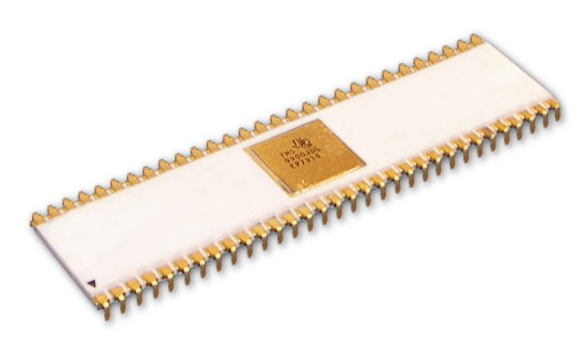
An ad for the TMS9900 which came out in 1976
KEY FEATURES OF THE TMS9900 |
|

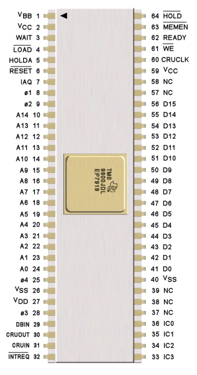
TMS 9900 PIN ASSIGNMENTS AND FUNCTIONS
| SIGNATURE | PIN | I/O | DESCRIPTION | ||
ADDRESS BUS |
|||||
A0 (MSB) |
24 |
OUT |
A0 through A14 comprise the address bus. |
||
A1 |
23 |
OUT |
This 3-state bus provides the memory |
||
A2 |
22 |
OUT |
address vector to the external-memory |
||
A3 |
21 |
OUT |
system when MEMEN is active and I/O-bit |
||
A4 |
20 |
OUT |
address and external-instruction addresses |
||
A5 |
19 |
OUT |
to the I/O system when MEMEN is inactive. |
||
A6 |
18 |
OUT |
The address bus assumes the high-impedance |
||
A7 |
17 |
OUT |
state when HOLDA is active. |
||
A8 |
16 |
OUT |
|||
A9 |
15 |
OUT |
|||
A10 |
14 |
OUT |
|||
A11 |
13 |
OUT |
|||
A12 |
12 |
OUT |
|||
A13 |
11 |
OUT |
|||
A14 (LSB) |
10 |
OUT |
|||
DATA BUS |
|||||
D0 (MSB) |
41 |
I/O |
D0 through D15 comprise the bidirectional |
||
D1 |
42 |
I/O |
3-state data bus. This bus transfers memory |
||
D2 |
43 |
I/O |
data to (when writing) and from (when |
||
D3 |
44 |
I/O |
reading) the external-memory system when |
||
D4 |
45 |
I/O |
MEMEN is active. The data bus assumes the |
||
D5 |
46 |
I/O |
high-impedance state when HOLDA is |
||
D6 |
47 |
I/O |
active. |
||
D7 |
48 |
I/O |
|||
D8 |
49 |
I/O |
|||
D9 |
50 |
I/O |
|||
D10 |
51 |
I/O |
|||
D11 |
52 |
I/O |
|||
D12 |
53 |
I/O |
|||
D13 |
54 |
I/O |
|||
D14 |
55 |
I/O |
|||
D15 (LSB) |
56 |
I/O |
|||
POWER SUPPLIES |
|||||
VBB |
1 |
Supply voltage (-5 V NOM) |
|||
VCC |
2, 59 |
Supply voltage (5 V NOM) |
|||
VDD |
27 |
Supply voltage (12 V NOM) |
|||
VSS |
26,40 |
Ground Reference |
|||
CLOCKS |
|||||
ø1 |
8 |
IN |
Phase-1 clock |
||
ø2 |
9 |
IN |
Phase-2 clock |
||
ø3 |
28 |
IN |
Phase-3 clock |
||
ø4 |
25 |
IN |
Phase-4 clock |
||
BUS CONTROL |
|||||
DBIN |
29 |
OUT |
Data bus in. When active(high), DBIN indicates that the |
||
TMS9900 has disbled its output buffers to allow the memory |
|||||
to place memory-read data on the data bus during MEMEN. |
|||||
DBIN remains low in all other cases except when HOLDA |
|||||
is active. |
|||||
MEMEN |
63 |
OUT |
Memory enable. When active (low), MEMEN indicates that |
||
the address bus contains a memory address. |
|||||
WE |
61 |
OUT |
Write enable. When active (low), WE indicates that memory |
||
write data is available from the TMS9900 to be |
|||||
written into memory. |
|||||
CRUCLK |
60 |
OUT |
CRU clock. When active (high), CRUCLK indicates that |
||
external interface logic should sample the output data on |
|||||
CRUOUT or should decode external instructions on A0-A2 |
|||||
CRUIN |
31 |
IN |
CRU data in. CRUIN, normally driven by 3-state or open |
||
collector devices, redeives input data from external interface |
|||||
logic. When the processor executes a STCR or TB |
|||||
instruction, it samples CRUIN for the level of the CRU input |
|||||
bit specified by the address bus (A3-A14). |
|||||
CRUOUT |
30 |
OUT |
CRU dat out. Serial I/O data appears on the CRUOUT line |
||
when an LDCR, SBZ or SBO instruction is executed. The |
|||||
data on CRUOUT should be sampled by external I/O interface |
|||||
logic when CRUCLK goes active (high). |
|||||
INTERRUPT CONTROL |
|||||
INTREQ |
32 |
IN |
Interrupt request. When active (low), INTREQ indicates that an |
||
external interrupt is requested. If INTREQ is active, the |
|||||
processor loads the data on the interrupt-code-lines IC0 through |
|||||
IC3 into the internal interrupt-code-storage register. The code |
|||||
is copared to the interrupt mask bits of the status register. If |
|||||
equal or higher priority than the enabled interrupt level |
|||||
(interrupt code equal or less than status register bits 12 |
|||||
through 15) the TMS9900 interrupt sequence is initiated. If |
|||||
the comparsion fails, the processor ignores the request. |
|||||
INTREQ should remain active and the processor will continue |
|||||
to sample IC0 through IC3 until the program enables a |
|||||
sufficiently low priority to accecpt the request interrupt. |
|||||
IC0 (MSB) |
36 |
IN |
Interrupt codes. IC0 is the MSB of the interrupt code, which is |
||
IC1 |
35 |
IN |
sampled when INTREQ is active. When IC0 through IC3 are |
||
IC2 |
34 |
IN |
LLLH, the highest external-priority interrupt is being requested |
||
IC3 (LSB) |
33 |
IN |
and when HHHH, the lowest priority interrupt is being requested. |
||
MEMORY CONTROL |
|||||
HOLD |
64 |
IN |
Hold. When active (low), HOLD indicates to the processor that |
||
an external controller (e.g., DMA device) desires to utilize the |
|||||
address and data busses to transfer data to or from memory. |
|||||
The TMS9900 enters the hold state following a hold signal when |
|||||
it has completed its present memory cycle. The processor |
|||||
then places the address and data buses in the high-impedance |
|||||
state (along with WE,MEMEN, and DBIN) and responds with a |
|||||
hold-acknowledge signal (HOLDA). When HOLD is removed |
|||||
the processor returns to normal operation. |
|||||
HOLDA |
5 |
OUT |
Hold acknowledge. When active (high), HOLDA indicates that |
||
the processor is in the hold state and the address and data |
|||||
buses and memory control outputs (WE,MEMEN, and DBIN) |
|||||
are in the high-impedance state. |
|||||
READY |
62 |
IN |
Ready. When active (high), READY indicates that memory |
||
will be ready to read or write during the next clock cycle. |
|||||
When no-ready is indicated during a memory operation, the |
|||||
TMS9900 enters a wait state and suspends internal operation |
|||||
until the memory systems indicate ready. |
|||||
WAIT |
3 |
OUT |
Wait. When active (high), WAIT indicates that the TMS9900 |
||
has entered a wait state because of a not-ready condition from |
|||||
memory. |
|||||
TIMING AND CONTROL |
|||||
IAQ |
7 |
OUT |
Instruction acquisition. IAQ is active (high) during any memory |
||
cycle when the TMS9900 is acquiring an instruction. IAQ can |
|||||
be used to detect illegal op codes. |
|||||
LOAD |
4 |
IN |
Load. When active (low), LOAD causes the TMS9900 to |
||
execute a nonmaskable interrupt with memory address FFFC |
|||||
containing the trap vector (WP and PC). The load sequence |
|||||
begins after the instruction being executed is completed. |
|||||
LOAD will also terminate an idle state. If LOAD is active during |
|||||
the time RESET is released, then the LOAD trap will occur |
|||||
after the RESET function is completed. LOAD should remain |
|||||
active for one instruction period. IAQ can be used to determine |
|||||
instruction boundaries. This signal can be used to implement |
|||||
cold-start ROM loaders. Additionally, front-panel routines can |
|||||
be implemented using CRU bits as front-panel-interface signals |
|||||
and software-control routines to control the panel operations. |
|||||
RESET |
6 |
IN |
Reset. When active (low), RESET causes the processor to be |
||
reset and inhibits WE and CRUCLK. When RESET is released |
|||||
the TMS9900 then initiates a level-zero interrupt sequence that |
|||||
acquires WP and PC from locations 0000 and 0002, sets all |
|||||
status register bits to zero, and starts execution. RESET will |
|||||
also terminate an idle state. RESET must be held active for |
|||||
a minimum of three clock cycles. |
|||||
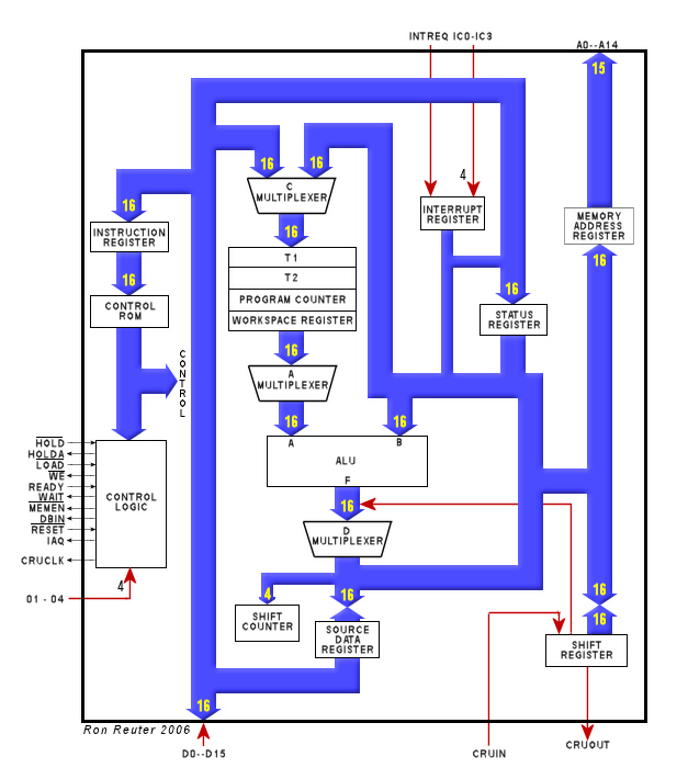
TMS 9900 ARCHITECTURE