 |
Replace Battery on Geneve 9640
|
The battery on a Geneve should last 3-5 years, but eventually you will need to replace it, especially since they
are all older than that! This is a pretty easy project and all you need is a 3 volt lithium cell with solder tabs
already applied.
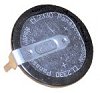
Do not try to solder tabs to a lithium cell as they can get hot enough to explode! The battery that
came with the geneve is a 2032 but the one used for the mini memory module will work fine. You can order a battery
here. Below is a picture of this battery
showing the solder tabs.
|

|
|
"If you are not an experienced desolder/solder type then
let someone else do your repair/upgrade as the GENEVE board can be tough for
beginners as it is a three layer board". Geneves are very RARE, and every board COUNTS!
|

|
|
Please make sure that all wiring and soldering is double checked before re-applying power. Though computer components are pretty hardy some do not take to being
wired up backwords or incorrectly. I have done my best to make sure that all diagrams
and instructions given here are correct, but I can not be responsible for any damage
an incorrect upgrade might cause. Also keep in mind that this will probably void any warranty :>).
|
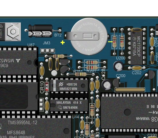
The above picture shows the battery on the Geneve. Simply desolder the battery and remove it. Be careful unsoldering
the positive side of the battery as it is easy to damage the solder pad. Don't fret if you do (ok, I will admit it, I
messed mine up), as there is a simple fix for that which will be mentioned later.
You will notice that the pad mentioned above does not seem to go anywhere,
and it doesn't. The Gevene board is a multi-layor board which means that there are traces that run inside the board.
The trace for the positive side of the battery is internal in the card.
|
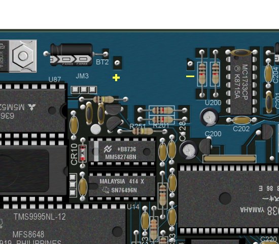
Notice in the picture above that I have marked the positive (+) and negative (-) solder pads on the circuit board.
Needless to say it is very important that you solder in the battery using the correct polarity. Solder in the new
battery, again being careful not to overheat the solder pad on the positive side of the battery.
If you were careful (and lucky!) then you are ready to test the battery. If the solder pad does come off then follow
the next step below.
|
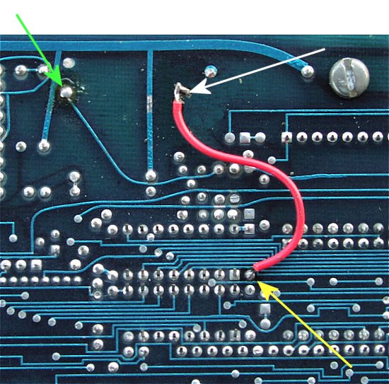
If you are joining me here then more than likely you need to add a jumper wire like I had to. No shame, it is very
easy to do. We will be soldering a wire from the positive side of the battery to the point, which is the anode of CR-10,
on the board shown by the yellow arrow in the picture above. We will be doing this on the solder side of the board.
For reference the white arrow is pointing to the positive side of the battery, while the green arrow is pointing at the negative
side of the battery.
|
Testing the New Battery
To test the battery, place the card into the PEB, following the correct procedures (PEB off at least 2 minutes, etc.).
Hook up the keyboard and monitor, and turn on the PEB. When MDOS boots, set the time and date. Turn off the PEB for
10 minutes or so, and turn it back on. If the time and date are correct then the battery is hooked up correctly.
|
