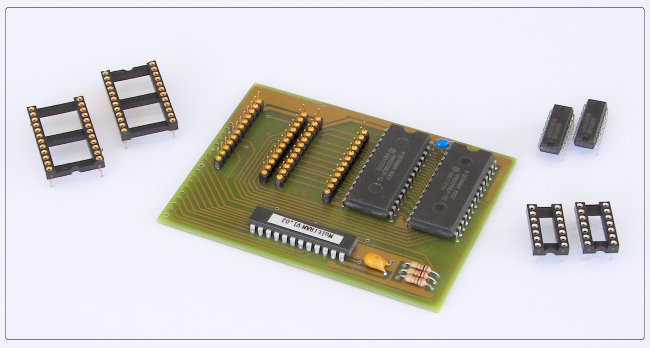
Above is the 32K on the 16 bit bus kit that I recieved from the TI GURU Richard Bell. The board was produced in Germany, and was designed
by TI-99 Hall of Fame member Michael Becker, Gerhard Danz and Harald Glaab. My pictures do not do the quality of this
board justice. This is one fine kit!
While I wouldn't call this an easy project it is NOT a difficult one, and could be completed by those with moderate
solding skills. I can assure you that it is MUCH easier than the other 32K in the console project I have on my site. Do
not let the amount of directions I have this site fool you. I just try to put as much information as I can, so those
you may not be as able with a soldering iron will know exactly what it entails to complete this project. I actually
completed the kit from text instructions which came on the supplied disk.
While discussing the directions, they were originally in german, and thanks to Fernando Lamas of the UK and
Bob Carmany of the USA for the execellent translation into english.
Though Richard Bell still has these kits on hand the supply is limited, so I would suggest that you get one on the way! The kits
cost $40, and they are well worth it. I assume there would be some shipping involved. I picked mine up at the last
TI faire, and of course the shipping was pretty cheap that way. Contact Richard Bell to order the board or for more information.
Richard can be contacted by email: swim4home@aol.com
The kit includes the board with HM62256LP RAM IC's, and the version 1.02 PAL (copyright SNUG 1990). 2 24 pin IC sockets,
2 74LS00 IC's and the sockets for these. The board comes assembled as shown above.
A great feature that this kit provides is the option to add three switch options. The first switch option adds the ability
to switch from from the 16 bit bus back to the standard 8 bit bus, and this option is highly recommened. The second
switch option allows you to expand the SCRATCH-PAD area from >8300 - >83FF to >8000 - >82FF. The third switch option
allows to enable 8K in the location >6000 - >7FFF (area normally used by modules). I did add the first option to my project. There is
more information in the included instructions about this options.
1. This device is not compatable with any other 32K memory expansion device installed
2. This device is not compatable with RAM disks that switch the memory area >2000 to 3FFF and >A000 to FFFF like
the CorComp and MYARC RAM disks. It is compatable with the Horizon and other similar RAM disks like the SNUG HRD-16 and
others.
|
Ok, enough talk about the kit, grab your soldering irons and lets get started!! Just be sure you read all the directions
first so you are familier with all the steps.
If you would like to view some instructions on taking apart the console go
here.
|
You will need a desoldering iron (or braid), a small tipped soldering iron with fine solder. You will also need some
AWG30 wire, plus the standard "working on electronics" hand tools. If you plan on installing any of the three switch options
then you will need 1 to 3 SPST switches.
|
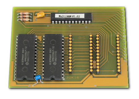
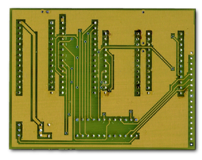
The above pictures show the front and back of the board.
|

Figure 1
The first step is to remove the two PAD RAM chips, MCM6810 as shown in figure 1. These will not be reused. Be careful
while removing the chips that you have all the solder cleaned up. You do not want to tear any of the traces.
Next locate the 74LS138 and remove pin 12 of this chip out of the motherboard. The yellow arrow in figure 1 is
pointing at this chip and the hole that is left when pin 12 is removed. This pin will not be used so be sure to snip
it off flush with the chip body. We will be soldering a wire in this hole later.
|
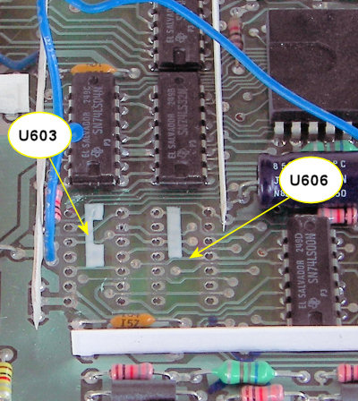
Figure 2
Next we will need to remove two 74LS00 at the locations U603 and U606 as shown in figure 2 above. Again be very careful
not tear any of the traces. These will not be reused.
Ok, that is the last of the deconstruction. The next steps will be the fun part of putting it back together.
|
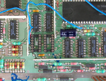
Figure 3
|
The next step is solder the two 14 pin sockets to the motherboard. While installing the sockets pay attention to the
orientation. Figure 3 shows the two sockets installed.
|
Next we will install the two 24 pin sockets to the motherboard. Figure 4 shows this. The pins on the board will actually
plug into these sockets.
|
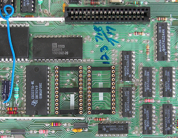
Figure 4
|
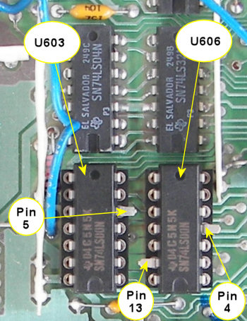
Figure 5
|
Before we insert the two 74LS00 into their sockets we will need to bend up some pins on them. On chip U603 pin 5 needs to
be bent up so it does not touch the socket. On chip U606 pins 4 and 13 will also need to be bent up. Figure 5 shows this.
Be sure when you insert the chips that they are correctly orientated.
|

Wiring
We will now need to run some wires from the board to different points on the motherboard. I found it much easier to run
the wires before I plugged the kit board onto the motherboard. Table 1 below shows where all the wires need to run to.
Where it says Switch Option you can refer to figure 8 below to determine where and what switches you wish to install.
Figures 6 and 7 will show you a graphic of where to run the wires, and you can use this as a double check
for the wiring. I used AWG 30 for the wiring on my board.
Also figures 6 and 8 below show the reference for PIN 1 on the kit board.
|
Pin 1 | | U602 Pin 2 | | Pin 10 | | U611 Pin 23 | |
Pin 2 | | U606 Pin 13 | | Pin 11 | | Switch Option | |
Pin 3 | | U606 Pin 4 and U603 Pin 5 | | Pin 12 | | U613 Pin 13 | |
Pin 4 | | Swith Option | | Pin 13 | | U504 hole of cutoff pin 12 | |
Pin 5 | | U605 Pin 3 | | Pin 14 | | U611 Pin 1 | |
Pin 6 | | U504 Pin 3 | | Pin 15 | | U611 Pin 19 | |
Pin 7 | | U504 Pin 2 | | Pin 16 | | U611 Pin 18 | |
Pin 8 | | U504 Pin 1 | | Pin 17 | | Switch Option | |
Pin 9 | | U611 Pin 22 | | Pin 18 | | Ground (switch option) | |
|
Table 1
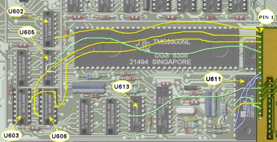
Figure 6
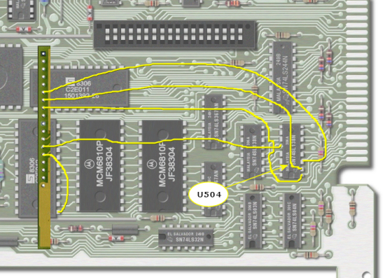
Figure 7
(I have removed part of the kit board for detail)
The Switches
There are three different switch options, and you may add none, 1,2 or all 3 if you wish.
SWITCH OPTION 1: This is an option which should be performed as it will allow the RAM (does not turn it off), to
revert back to the 8 bit bus, which would be like any 32K ram cards that would be installed in the PEB. Some software
does not like the RAM being on the 8 bit bus. (see notes below). You will need to run the wires from the switch to pin
18 (GROUND), and pin 17. Figure 8 shows the correct wiring.
SWITCH OPTION 2: This option allows you expand the SCRATCH-PAD from >8300 - >83FF to >8000 - >83FF. Now I am way to
dumb to have a clue what this does, but I assume for some the guru's this would be a good thing. Read the "Special Features"
section in the included instructions for more information on this. You will need to run the wires from the switch to
pin 18 (GROUND), and pin 11. Figure 8 shows the correct wiring.
SWITCH OPTION 3: This allows you to enable 8k RAM in the location >6000 - >7FFF (the area normally used by modules).
You will need to run the wires from the switch to pin 18 (GROUND), and pin 4. Figure 8 shows the correct wiring.
When switched on the space will be disabled in the module and enabled in the internal RAM. Some disk copy programs
like this feature (now this I do understand :>).
|
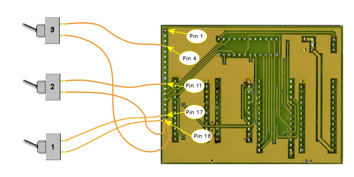
Figure 8
Wrapping up and Testing
After all the wires have been connected, and you are sure that all is in order you can plug the kit board onto the
motherboard. Before I reinstalled everything back into the case, I gave it a quick try. I have not had any problems
running my motherboards for a few seconds without heatsinks, but do this at your own risk. I hooked my board to
the monitor, and power supply (make sure it is off). Also make sure you don't have any metal pieces under the motherboard
or power supply. I also plugged in an Extended Basic cart before I applied power. Now turn on the monitor and let it warm
up for a moment or two, and then turn on the power. If you hear any wierd sounds, or nothing shows up on the screen, then
turn off the power immeditaly and re-check all the connections.
If everything looks good (we will assume it will), then choose extended basic at the menu and type "SIZE" at the prompt. If
everything went well, then you should see something like this: 13XXX BYTES STACK FREE, 24XXX BYTES OF PROGRAM SPACE FREE. As
soon as you see the above message turn off the console power so we don't overheat the VDP chip.
There... you did it!
Now you can put everything back together. Before putting the shielding back on the motherboard, apply some strips of electrical tape
to the inside of the shield where the kit board is. This will keep it from shorting. DO NOT put the tape on the board,
itself.
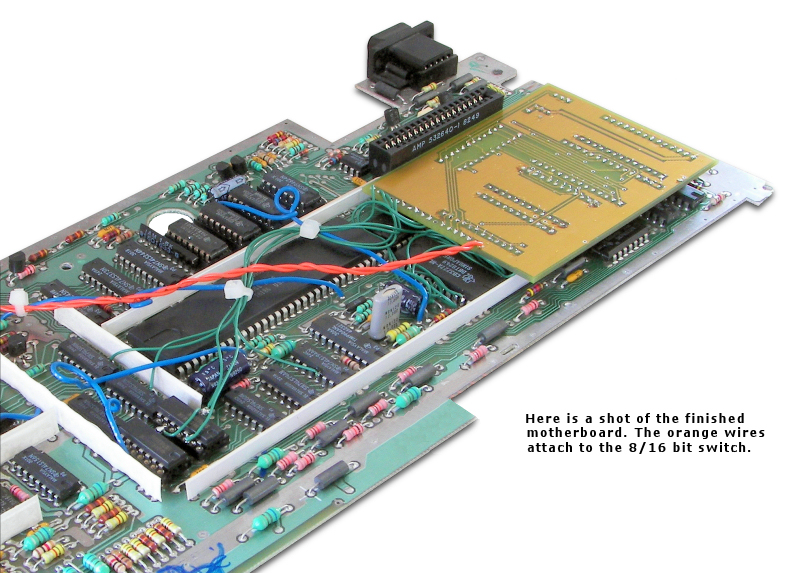
Also if you added some switches you will need to route the wires out of the shielding and find a place in the case where you can
mount the switches, as you want to be able to switch them.
While you are at it, you may wish to complete a couple other projects which would be complimentary with this project.
The first is the crystal upgrade project and
the Flex card tune up
This should make for a pretty "HOT" console!
|
Some notes from Richard Bell:
I just want to take a moment to share some of my experience
with using the 32K16 board for some time now. It is likely
that you will run into problems with programs and hardware
while using this device. I don’t give up right away, instead
experiment a little.
I’ll give you an example. I had a
problem trying to run my 32K16 console hooked up to a P-Box
that had a P-GRAM card in it. Whenever I tried to run an
X-Basic program that would access the P-GRAM clock it would
run a while and crash. By accident I found that rearranging
the cards in the P-Box so that the P-GRAM was next to the
interface card instead of next to the disk controller card
stopped the crashing. In other words as Michael would say
"We are in the hearth of the TMS9900" and so timing that we
would not normally find an issue with suddenly becomes an
issue.
Believe it or not, sometimes running at 3.58 MHz
works better than running at 3.0 MHz. The exception being
things like terminal programs unless you have a modified
table in your RS232 card. Most assembly programs work real
well with the 32KW and the Basic, X-Basic programs that
crash with the 32Kl6 can often he helped with a little
experimenting. It’s highly recomended to install the 8/16 bit
switch so you can slow down your system when required. Have
fun and enjoy your 32K16!
Regards, Richard Bell
Note: All switches are syncronized and may be toggled even if
the system is powered tip including the 8/16 bit speed switch.
This is the ONLY 321K16 available with this feature!
|